


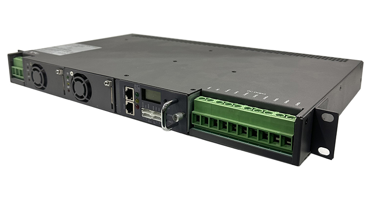
1U Rack Mount 3000W DC Power Supply 220V 48V Telecom Dual Rectifier System for Industry 60A Output Current 1500W Power 48VDC
- Input Voltage:220 V
- Output Current:60 A
- Output Voltage:48 V
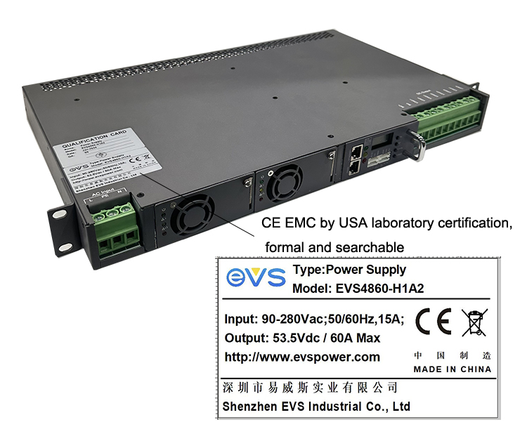
- Model Number:EVS4860-H1A2
- Brand Name:EVS
- Place of Origin:Guangdong, China
- Application:Industry, Laboratory, Industrial Equipment, Machines, Battery Charging
- Efficiency:0.95
- Output Frequency:50/60 Hz
- Output Type:Single
- Protection:Short Circuit Protection, Overcurrent Protection, Overvoltage Protection, Over Temperature Protection, Overloading Protection, Over Power Protection, Undervoltage Protection, Overcharging Protection
- Type:AC-DC, DC-DC
- Apllication:Telecom power
- anti-theft:Module loss report
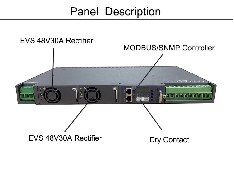
- Monitoring module:hot swappable
- Features Dry contact:webrowser SNMP
- Mounting Type:19 Rack mounted
- Output Power:60A
- Color:customized
- Packing:Carton Box
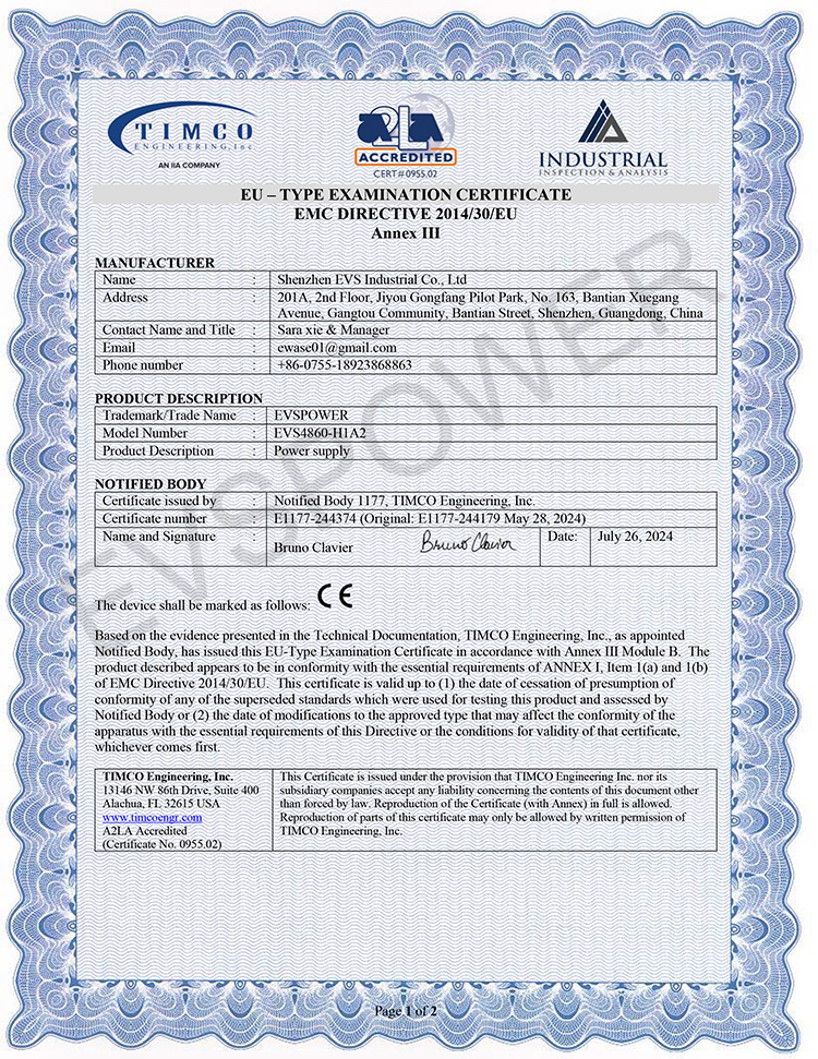
- Certificate:CE RoHS


EVS Telecom Dual Rectifier 1u dc power supply
EVSPOWER1u dc power supply in Telecom Power: Redundancy, Reliability, and Efficiency
1. Introduction
In mission-critical telecom and industrial applications, uninterrupted power supply is non-negotiable. Dual rectifier switching power systems have emerged as a gold standard for 48V DC power distribution, combining redundancy, high efficiency, and scalability. This article explains how dual rectifier systems work, their advantages, and why they are indispensable for modern infrastructure.
2. What is 1u dc power supply?
A dual rectifier system integrates two independent rectifier modules in parallel within a single power shelf. Each rectifier converts AC input to regulated 48V DC output while sharing the load or operating in redundancy mode.
Key Components:
AC-DC Rectifiers: High-efficiency switching modules (e.g., 3kW/6kW units).
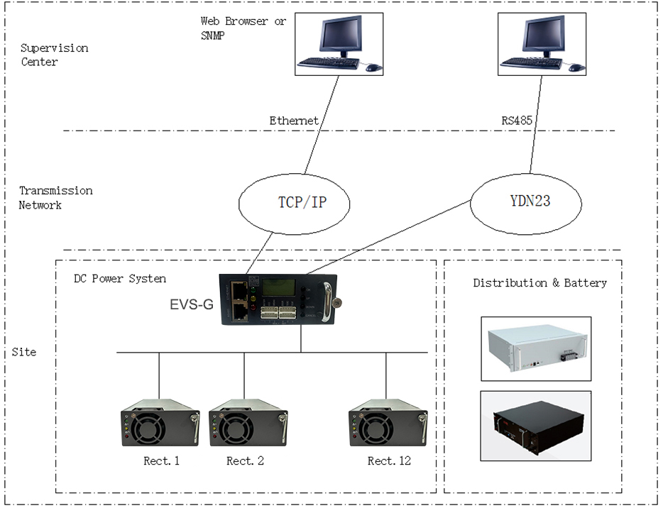
Controller: Manages load sharing, fault detection, and battery charging.
Hot-Swap Design: Modules can be replaced without system shutdown.
3. Why Dual Rectifiers? Key Advantages
3.1 Redundancy for Maximum Uptime
N+1 Redundancy: If one rectifier fails, the other instantly takes the full load, ensuring zero downtime.
Critical for 5G/Edge Sites: Supports always-on networks for IoT, smart cities, and real-time communication.
3.2 High Efficiency and Energy Savings
Advanced Switching Topology: >95% efficiency (e.g., LLC resonant conversion).
Dynamic Load Sharing: Optimizes power distribution between rectifiers to minimize losses.
Example:
A 10kW dual-rectifier system saves 500+ kWh/year compared to legacy linear systems.
3.3 Scalability and Flexibility
Modular Design: Add rectifiers as power demands grow (e.g., from 3kW to 30kW).
Wide Input Range: Supports 90–300V AC, ideal for unstable grids in emerging markets.
4. Applications in Telecom and Beyond
4.1 Telecom Base Stations
Powers Remote Radio Units (RRUs), BBUs, and fiber optic equipment.
Integrates seamlessly with -48V battery backup systems.
4.2 Data Centers
Supports Open Compute Project (OCP) 48V DC architectures.
Reduces energy costs by eliminating multiple AC-DC conversions.
4.3 Industrial IoT and Renewable Systems
Compatible with solar/wind hybrid setups for off-grid sites.
This1u dc power supply is for commucication,
Output voltage -54V,Output current 0-60A;Its features include input over/under-voltage protection, output over-current protection, output over-voltage protection.
EVS1u dc power supply ,dc power supply , with the following features and functions:
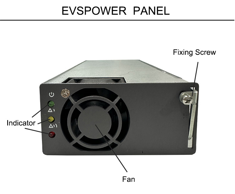
2. Hot swappable and Plug and Play;
3 .N+1 redundancy,each module available in 30A@48Vdc;
4 .AC /DC distribution system for AC input/ DC output distribution and protection;
5. RS485, Modbus,SNMP communication for remote control;
6.Compact design and embedded modular system, support power system and module sleep, efficient mixing, energy saving;
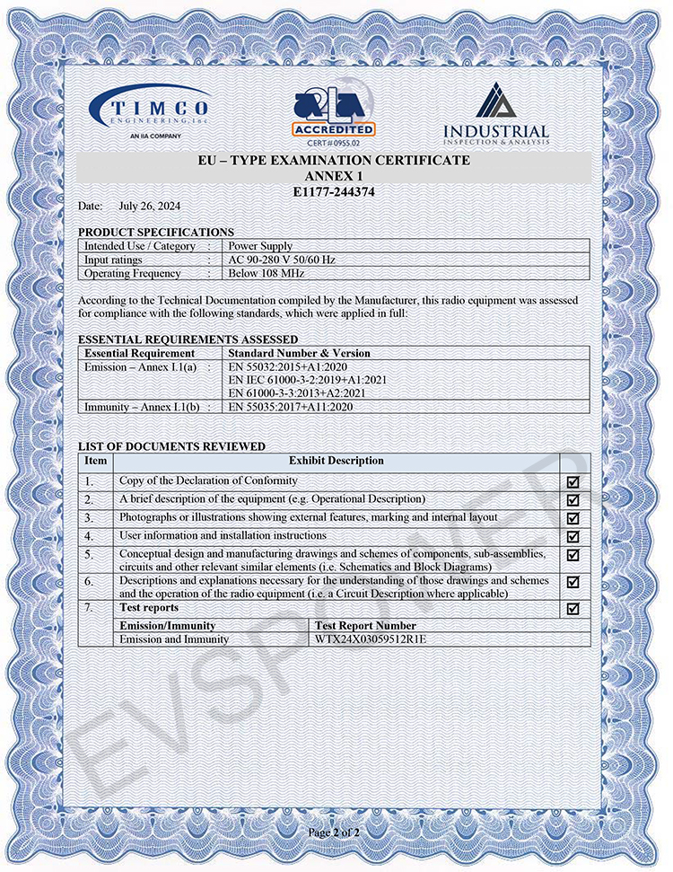
7.High Efficiency with low EMI. CE Safety and EMC certification
8. the system has high power factor greater than 0.98;
9. there are input under voltage, input voltage, output voltage, output current limiting, output short circuit, over temperature protection;
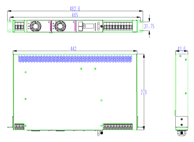
10.Small size, height 1U, 2*48V30A evspower rectifier module
7.Telecom power system Electrical Characteristics:
| 1 | evspower 1u dc power supply Input Characteristics | ||||||||||
| No. | Items | Technical Specifications | Unit | Remarks | |||||||
| 1.1 | Input rated voltage | 200—240 | Vac | ||||||||
| 1.2 | Input voltage range | 90—290 | Vac | OR 100-400VDC | |||||||
| 1.3 | Input Current | ≤20 | A | Lowest input voltage, rated load | |||||||
| 1.4 | inputvoltage frequency | 50/60 | Hz | ||||||||
| 1.5 | Power factor | ≥0.99 | rated input voltage, rated load | ||||||||
| 1.6 | Input Shock Current | ≤30 | A | 264Vac | |||||||
| 2 | Output Characteristics | ||||||||||
| No. | Items | Technical Requirements | Unit | Remarks | |||||||
| 2.1 | Output Rated Voltage | 54 | Vdc | ||||||||
| 2.2 | Output current range | 0—60 | A | Inutpu voltage:176—290Vac. | |||||||
| 0—30 | A | Inutpu voltage:90—175Vac | |||||||||
| 2.3 | Output voltage range | 53.5 | Vdc | ||||||||
| 2.4 | Efficiency | ≥96% | 220Vac input,output 54Vdc/60A. | ||||||||
| ≥92% | 110Vacinput ,output54Vdc/30A. | ||||||||||
| 2.5 | Output ripple & noise | ≤200 | mVp-p | Rated load, frequency band is limited to 20MHz | |||||||
| 2.6 | Turn-on output delay | 3—8 | S | Vin=220Vac | |||||||
| 2.6 | Output rising time | ≤200 | mS | Output voltage rises from 10% to 90%, rated load. | |||||||
| 2.7 | Turn on/off overshoot | ≤±5 | %Vo | ||||||||
| 2.8 | Combined regulation | ≤±1% | |||||||||
| 2.10 | Transient Response | Overshoot | ≤ ±5 | %Vo | 5%—50%—25% or 50%—75%—50% load change. | ||||||
| Recovery time | ≤ 200 | µS | |||||||||
| 2.11 | Phone weighed noise voltage | ≤2 | mV | ||||||||
| 2.12 | p-pk value noise | ≤400mV | 0—300KHz | ||||||||
| 2.13 | Wide frequency noise voltage | ≤100 | mV | 3.4—150KHz | |||||||
| ≤30 | 0.15—30000KHz | ||||||||||
| 2.14 | Disperse noise | ≤5 | mV | 3.4—150KHz | |||||||
| ≤3 | 150—200KHz | ||||||||||
| ≤2 | 200—500KHz | ||||||||||
| ≤1 | 500—30000KHz | ||||||||||
| 3 | Battery Management Characteristics | ||||||||||
| No. | Items | Technical Requirements | Unit | Remarks | |||||||
| 3.1 | Floating charge current limiting | 10±1.5 | A | ||||||||
| 3.2 | Battery undervoltage protection point | 42.5—43.5 | V | Cut load,protect battery | |||||||
| 4 | Other Characteristics | ||||||||||
| No. | Items | Technical Requirements | Unit | Remarks | |||||||
| 4.1 | MTBF | 100,000 | H | ||||||||





FAQ
 Single Output AC-DC 2000W Engine Room Telecom Rectifiers 60A for Outdoor Base Station Industry Application
 High Efficiency 48VDC Telecom Power System with 30Amp Rectifier and Integrated Web Browser Access
 EVS48100 48V DC Power Systems 100A Rear Embedded Telecom Rectifier 50A/100A 220V Input Voltage for Industrial Use
 High Power 3000W 48Vdc Pfc AC DC Switching Power Supply Single for Motor Compressor for Industrial Automotive Applications